

Dual beam Irradiation for FUsion materials (DiFU)
All ion beams that can be produced by any of the two RBI accelerators can be directed into the Dual beam Irradiation for FUsion materials (DiFU) chamber.
The Dual beam Irradiation for FUsion materials (DiFU) chamber is originally developed for dual beam irradiation of fusion materials, but can be used for irradiation of other sample types using wide range of ion beams.
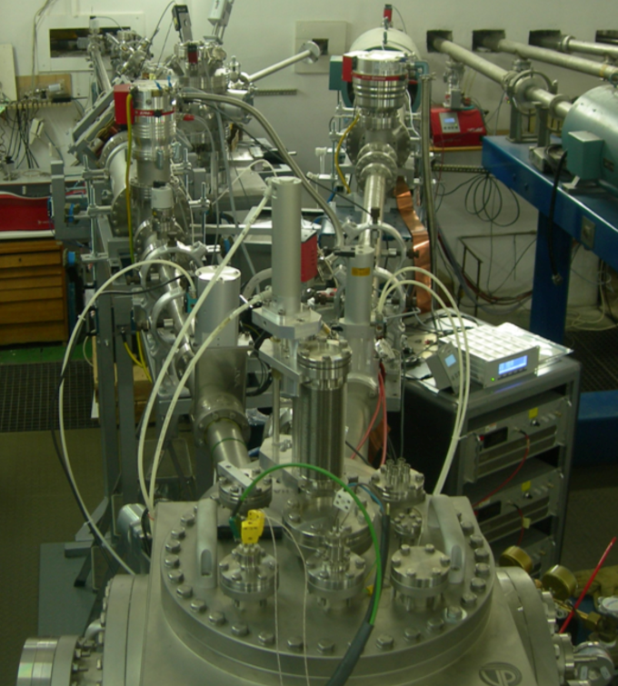
Dual beam Irradiation for FUsion materials (DiFU) end station
The ion beams (mm sized spot sizes) from two accelerators are entering the chamber under the 17-degree angle. Beams are scanned by electrostatic deflectors over the sample surface up to the area of 30 x 30 mm2. Sample temperature (during irradiation) can be controlled up to 800 °C. In order to enable irradiation of materials/samples having different geometries, working principles and purposes, this scattering chamber is of fairly large dimensions (40 cm cube). Each of the ion beams can pass through the rotating beam degrader in order to homogenize the irradiation over larger sample depths. The automatic retractable Faraday cups are used to monitor the beam current stability and fluence when inserted. The position and stability of the beam during irradiation can be monitored by picoammeters connected to the slits at the chamber entrance.
Ion energy:
The final energy of the ion is determined by the high voltage produced by the tandem accelerator that provides the ion acceleration. Tandem accelerators require injection of negative ions to provide acceleration using the positive potential of the terminal. After the first stage of acceleration, negative ions are stripped inside the terminal and resulting positive ions are then accelerated again by the same potential difference to the ground potential at the other side of the accelerator. In the case of proton acceleration, 1 MV terminal voltage will enable acceleration of first negative hydrogen ions and second positive ions/protons to the final energy of 2 MeV. In the case of heavier ions that can be stripped to higher charge states (q) the final ion energy (E in MeV) obtained by high potential (V) will be E=V*(1+q).
The accessible high voltage ranges at RBI accelerator facility are: 0.1 to 1.0 MV for the 1.0 MV Tandetron accelerator and from 0.5 to 4.0 MV for the Tandem Van de Graaff. Although Tandem Van de Graaff is nominally a 6 MV accelerator, it could presently obtain voltages higher than 4 MV only after increasing the pressure of insulation gas, which is currently not possible due to technical and administrative limitations.
Ion currents:
Majority of routinely used ion beams that are accelerated by any of the ion sources and any of the two available accelerators are possible to reach currents of the 1 mA order (H, He, Li, C, O, Si, Cl, Cu, I, Au). However for the most of ion beam applications, currents of the order 1–100 nA are mostly used. Ion currents for other elements/isotopes mainly depend on the efficiencies of sputtering ion sources (NEC SNICS and SNICS40) in providing the negative ion beams for the particular element.
Ion beam scanning/current measurement:
Ion beam can be scanned by fast electrostatic scanners over the area of 30 x 30 mm2. Beam current is monitored by occasional interruption of irradiation by Faraday cups. Symmetry in irradiation is monitored by 4 slits around each of the two ion beams.
Beam degraders:
In order to avoid irradiation by monoenergetic beam, which produces an inhomogeneous profile of implanted ions and radiation damage (around the Bragg peak), the entrance to the irradiation chamber from the both beam lines is equipped by beam degraders. It consists of a series of foils of different thicknesses, mounted on a rotator that intercepts the beam in front of the sample being irradiated. Thicknesses of metal foils (e.g. 0.65 to 7 µm thick Al) are selected in a way to spread the ranges of ions over a larger depth scale.
Sample holder:
Sample holder can accept samples of different sizes, but the XYZ manipulator has certain limitations in movement. These limitations are 100 mm for X and Y and 50 mm for Z axis. XYZ positioning is performed by custom software which is also able to scan the sample in front of the beam. Resistive heater can heat the samples up to 800 °C, as monitored by thermocouples and IR camera. A system of cameras is used to enable appropriate sample positioning.